

 |
|
Planning a trip to Sicily? Then, make sure you won't be feeding the Mafia!  |
| Home | Scientific Products | RF Communications Products | Contact |
|
If you have a scientific interest in the physics of the radio, you should browse this site as an e-book! |
|
NB: this page is an appendix to the Marconi's Nobel lecture page |
||||||||||||||||||
Fessenden and Marconi: their differing technologies and transatlantic experiments during the first decade of this centuryby John S. Belrose 1. Introduction Many scientists and engineers have contributed to the early development of electromagnetic theory, the invention of wireless signaling by radio, and the development of antennas needed to transmit and receive the signals. These include, Henry, Edison, Thomson, Tesla, Dolbear, Stone-Stone, Fessenden, Alexanderson, de Forest and Armstrong in the United States; Hertz, Braun and Slaby in Germany; Faraday, Maxwell, Heaviside, Crookes, Fitzgerald, Lodge, Jackson, Marconi and Fleming in the UK; Branly in France; Popov in the USSR; Lorenz and Poulsen in Denmark; Lorentz in Holland; and Righi in Italy. The inventor of wireless telegraphy, that is messages as distinct from signals, is Italian-born Guglielmo Marconi, working in England; and the inventor of wireless telephony is Canadian-born Reginald Aubrey Fessenden, working in the United States. According to Marconi, he was an amateur in radio: in fact this was far from the truth. He foresaw the business side of wireless telegraphy. He was aware, however, of his own limitations as a scientist and engineer, and so he enlisted (in 1900) the help of university professor John Ambrose Fleming, as scientific advisor to the Marconi Company; and he chose engineers of notably high caliber, R.N. Vyvyan and others, to form the team with which he surrounded himself. Marconi's systems were based on spark technology, and he persevered with spark until about 1912. He saw no need for voice transmission. He felt that the Morse code was adequate for communication between ships and across oceans. He was a pragmatist and uninterested in scientific inquiry in a field where commercial viability was unknown. He, among others, did not foresee the development of the radio and broadcasting industry. For these reasons Marconi left the early experimentation with wireless telephony to others, Reginald Fessenden and Lee de Forest. Fessenden was a radio scientist and an engineer, but he did not confine his expertise to one discipline. He worked with equal facility in the chemical, electrical, radio, metallurgical and mechanical fields. He recognized that continuous wave transmission was required for speech and continued the work of Nikola Tesla, John Stone-Stone, and Elihu Thomson on this subject. Fessenden also felt that he could transmit and receive Morse code better by the continuous wave method than with the spark apparatus that Marconi was using. This paper overviews the differing technologies of Fessenden and Marconi at the turn of the century, and their endeavours to achieve transatlantic wireless communications.
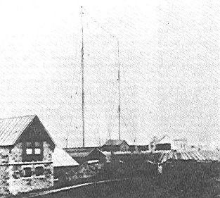
2. Transatlantic wireless communications began at LF Heinrich Hertz's classical experiments were conducted in his laboratory using a small end-loaded dipole driven by an induction coil and a spark gap for his transmitter. His receiver was a small loop, and detection was by induced sparking. Since the frequency generated by a spark transmitter is determined by the resonant mean frequency of the antenna system, his experiments in 1887 were conducted at VHF/UHF (60 to 500 Mhz) -- the corresponding wavelengths (5.0 to 0.6 metre) being practical for indoor experiments. Marconi started experimenting with Hertz's apparatus in 1894. He was fascinated by the idea that by means of Hertzian waves it might be possible to send telegraph signals, without wires, far enough for such a system to have commercial value. By 1896 he achieved a transmission distance of 2.5 kilometres, by using an earth and an elevated aerial at both transmitter and receiver (nowadays called a Marconi antenna). His first permanent station established a link between the Isle of Wight and Bournemouth, England, some 22 km away (in 1897). He established communications across the Channel in 1899. By now he must have been using frequencies in the low HF band, since his aerial systems were much larger. In 1900 he decided to try and achieve transatlantic communications. The required aerial size, and so the signalling frequency, at best could only be projected by extrapolation from values successful over a range of much shorter distances. The aerial at Poldhu, Cornwall in December 1901 (see Fig. 1), more by circumstance than design (to be discussed), radiated signals in the MF band (about 850 kHz). Marconi kept building larger antenna systems, larger since he was striving for greater transmission distance and improved signal reception, which lowered the operating frequency. At Poldhu the frequency of his station in October 1902 was 272 kHz. His initial station at Table Head, Glace Bay, NS in December 1902 was a massive structure comprising 400 wires suspended from four 61 metre wooden towers, with down leads brought together in an inverted cone at the point of entry into the building. The frequency was 182 kHz. By 1904 his English antenna had become a pyramidal monopole with umbrella wires, and the frequency was 70 kHz. In 1905 his Canadian antenna, moved to Marconi Towers, Glace Bay was a capacitive top-loaded structure, with 200 horizontal radial wires each 305 metres long, at a height of 55 metres, and the frequency was 82 kHz. By late in 1907 he was using a frequency of 45 kHz. Fessenden's early experiments using spark transmitters were probably conducted at a frequency in the lower part of the HF band, since initially he was testing over short links of a few kilometres using 50-metre masts to support wire aerials. His belief was that radio transmission should be by way of continuous waves (CW), not the damped-wave or whip-and-lash type of transmission provided by spark-gap transmitters. The only way he knew to generate true CW was by a high-frequency alternator, and in the period 1890-1905 10 kHz was the highest frequency achieved using an HF alternator. But the efficiency of practical aerial systems was very poor at such a low frequency. So he strove to increase the speed and frequency of his HF alternator. In the meantime he invented the synchronous rotary-spark-gap transmitter. His transatlantic experiments in 1906 were conducted using such a transmitter and 420-foot umbrella top loaded antennas at Brant Rock, MA and Machrihanish, Scotland, tuned to a frequency of about 80 kHz. 3. Marconi and Fessenden Their Differing Technologies Marconi, those working with him, and most experimenters in the new field of wireless communications at the turn of the century, were unanimous in their view that a spark was essential for wireless, and he actively pursued this technology from the beginning (in 1895) until about 1912. Fessenden was a proponent of the continuous wave (CW) method of wireless transmission. Somewhat alone in this direction in 1900-1906, his CW patents had little impact on the users of radio technology. The golden age for spark was from 1900 to 1915; dominated by Marconi, who fought to quell any divergence from that mode. The fact that the damped wave-coherer system could never be developed into a practical operative telegraph system and that the sustained oscillation method should be used was perceived by Fessenden in 1898 [see Electrical World, July 29, August 12, September 16, 1899 and Proceedings American Institute of Electrical Engineers, November, 1899, p. 635 and November 20, 1906, p. 7311. In 1900-1902 only two methods were available for generating CW: 1) the HF alternator; and 2) the oscillating arc. Plain Aerial Apparatus Marconi's early experiments employed plain aerial apparatus, and placed the spark gap directly across the terminals of his vertical wire aerial-ground antenna. His receiver employed a similar set-up, with a coherer type of detector. The transmitter/receiver systems were untuned, excepting by the natural amplitude-frequency response of the aerials. Unbeknownst to him his transmitter and receiver were in effect "tuned" to different frequencies. The oscillating damped wave on the transmitting aerial, which was in effect "connected" to ground through the low resistance of the conducting spark, was in effect "tuned" to the fundamental quarter wave resonant response of the aerial. His receiver however, awaiting reception of the spark signal, would in effect be tuned to the half-wave resonant frequency of the wire aerial -- since the coherer prior to the reception of the RF impulse-like signal would present a high impedance between the aerial and ground. This problem was solved by using a closed tuned circuit for the receiver; and for the transmitter by using the circuit arrangement devised by Braun, in which the oscillatory circuit (discharge capacitor and spark gap) was placed in a separate primary circuit transformer-coupled to the antenna system. This latter arrangement also lengthened the duration of the damped wave signal, since when the spark ceased, the oscillation in the antenna circuit continued, damped only by its natural L-C-R response.
Transmitter Technology The Poldhu transmitter was a curious two-stage circuit, in which a first-stage spark at some attainable lower voltage provided the energy for the second stage in tandem (Fig. 2), to spark at a specified higher voltage. While this voltage multiplication system was innovative in the field of wireless at the time, it carried with it many problems, and the inefficiencies of two spark stages. Marconi clearly realized that to achieve high power from a spark transmitter it was necessary to charge the condenser to a very high voltage (voltages of up to 150 kV were spoken about and may have been realized); and that a very large discharge capacitance was needed, since the stored energy in the condenser was understood (Energy equals 1/2 CV2). But he carried the latter requirement to an extreme. The power capability of the Poldhu AC generator (25 amperes at 1500 volts) in 1901 was quite insufficient to recharge the condenser every period. It seems like several periods of the supply generator (operating at 36 Hz) were required to bring the condenser voltage to gap break-down potential. Fleming's estimates of the spark rate lie between wide limits. Thackeray [1992] has estimated that the spark rate for the primary circuit was 7.5 to 12 sparks/sec at most; and the spark rate for the secondary circuit might have been as low as two or three sparks/sec. After that time there was clearly a redesign to a single-stage transmitter that sparked directly from the power transformer; and Fleming began to develop rotating dischargers in an attempt to achieve rapid quenching of the spark. It is perhaps ironic that the low spark rate was compromised by Marconi himself, when in Newfoundland he put a telephone receiver to his ear to listen for the dot transmissions from Poldhu. At the low spark rate he employed all he would hear would be a click, not distinguishable from an atmospheric. But recall that Marconi's early experience was with coherer-type detectors, which worked best when the spark rate was low.
Before leaving our discussion about Marconi's methodology, let me comment on some of the physical arrangements for his stations. The discharge capacitor for his Clifden and Marconi Towers, Glace Bay stations consisted of thousands of steel plates hanging from floor to ceiling, which filled the wings of the building, and this room was subsequently called the "condenser building" (see Fig. 3). The power supply was a 15 kV DC generator (three 5 kV generators in series) driven by a steam engine. Note the power source was DC. Standby batteries (6000, 2 volt, 30 AH batteries in series) at both stations may well have been the largest battery the world has ever seen. The heart of his Clifden/Marconi Towers stations was a whirling five foot spark discharge disk, with studs on its perimeter. Each time a stud passed between two electrodes, a 15 kV spark jumped the gaps. The regular spark rate was about 350 sparks/sec. The awesome size of the station and the din of the transmitter must have been something to behold. The power consumed by these stations was in the range of 100 to 300 kW, and the spark was a display of raw power. It is said that the awesome din of the transmitter could be heard several kilometres away. Fessenden's technology and circuit arrangements were very different. He tried all the various methods of generating wireless signals in the early days, by spark, by arc and by the high frequency alternator. It is likely that he would have used the HF alternator from the outset, see for example his patent No. 706,787 filed 29 May 1901; excepting that a suitable HF alternator, generating frequencies above about 10 kHz was not available until 1906. There is no fundamental reason that long distance wireless communications could not have begun at VLF, except for the practical realization of efficient antenna systems for such a low frequency. Fessenden's work was dominated by his interest in transmitting words without wires. By 1903 and 1904 fairly satisfactory speech had been transmitted by the arc method, but the news of Marconi's attempts to achieve transatlantic wireless telegraphy transmission had caught the attention of the world. Since the development of his HF alternator was taking longer than anticipated, Fessenden set his mind to make a more CW-like spark transmitter. This led to the development of the synchronous rotary-spark-gap transmitter. An AC generator was used, driven by a steam engine, which as well as providing the energy for the spark transmitter, was directly coupled to a rotating spark gap so that sparks occurred at precise points on the input wave, viz. at waveform maximum for best efficiency. The spark was between fixed terminals on the stator and terminals on the rotor, which was in effect a spoked wheel, rotating in synchronism with the AC generator. As the speed of the wheel and the AC frequency both depend on the speed of the generator, the number of times/sec at which the condenser voltage reaches a peak value and the number of opportunities it has for discharging can be made equal, and the positions of the stator terminals can be arranged so that these conditions occur simultaneously. Another advantage was realized, since in effect a rotary gap was a kind of a mechanically quenched spark-gap transmitter. The oscillations in the primary circuit ceased after a few oscillations, when the rotating gap opened. The quenched gap was more efficient and certainly less noisy than the unquenched gap. With a synchronous spark-discharger phased to fire on both positive and negative peaks of a 3-phase waveform, precisely at waveform peak, a 125 Hz generator could produce a spark rate of 750 times a second. These rotating gaps produced clear almost musical signals, very distinctive and easily distinguished from any other signal at the time. It was not true CW but it came as close as possible to that, and the musical tone could be easily read through noise and interference from other transmitters. Fessenden's Brant Rock and Machrihanish stations employed a rotary gap 1.8 metres in diameter at the rotor. Its rotor had 50 electrodes (poles) and its stator had four. It was driven by a 35 kVA alternator, powered by a steam engine. The synchronous rotary gap spark discharger should not be confused with the asynchronous rotary gap that was in more general use at the time (e.g. by Marconi ship-borne equipment, and radio amateurs in general used asynchronous rotary gaps). Here the speed of rotation of the wheel is entirely independent of the speed of the generator, and while it was possible to realize several sparks during one cycle of the generator, the sparks occur at different points on the cycle. The conditions are not exactly repeated each time as in the case of the synchronous spark, because the charging current from the generator is charging up the condenser during different parts of its own cycle of variation, and hence neither the voltage to which it is charged, nor the breakdown voltage is constant. Not only is it possible to miss a spark altogether, but the interval between sparks is not absolutely constant. In addition, the energy stored in the condenser and the proportion radiated in the separate wave trains is variable. The result is that the note heard at the receiving station is impure. By the summer of 1906 many of the difficulties had been overcome and the Alexanderson HF alternator developed by GE for Fessenden giving 50 kHz was installed at Brant Rock. Various improvements were made by Fessenden and his assistants, and by the fall of 1906 the alternator was working regularly at 75 kHz with an output of one half a kilowatt. This was the beginning of pure CW transmission, c.f. Alexanderson [1919]. Continuous waves was the method of generation Fessenden had long sought, since he wanted to transmit words without wires. He inserted a carbon microphone in series with the lead from his alternator to the antenna, and he had an amplitude modulated transmitter. But more on that later.
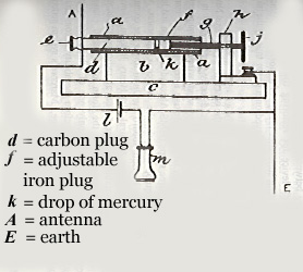
Receiver Technology The ability to receive wireless signals at the turn of the century was very poor, for several reasons: 1) Initially the receiver was untuned or if tuned the selectivity was poor; 2) there was no means to amplify the signal; and 3) a sensitive detector had yet to be invented. The early experiments employed a device called a coherer. The coherer as we have noted was a device which normally exhibited a high resistance, but when subject to a voltage above a given threshold there was a marked decrease in this resistance. The change in resistance could be detected by means of a secondary relay circuit, or by listening to the current change with a telephone earpierce. The filings coherer was a bistable device. It needed an electrical voltage to effect one transition, and a physical shock (a tapper) to return it to its initial state. The sensitivity of the device was poor; the action of the receiver depended upon a voltage rise and so was independent of the energy of the signal; it did not discriminate between impulses of different character, viz. between signals and atmospherics; the selectivity of the receiver was a function of the state of the coherer; and it could not be used as a detector for continuous waves. For his transatlantic experiment in 1901 Marconi had two types of receivers, and three types of coherers. One was a tuned receiver, which he referred to as a "syntonic receiver", that is a receiver tuned to the frequency of the transmitter. The second earlier receiver was untuned. The three types of coherers that he used were: one containing loose carbon filings; another designed by Marconi containing a mixture of carbon dust and cobalt dust; and thirdly the Italian Navy coherer (see Fig. 4) containing a globule of mercury between a carbon plug and a moveable iron plug. This latter device, when critically adjusted or more or less by luck, acted like a crude form of a rectifier, but its performance was poor and unpredictable [Phillips, 1993]. Later, in 1902, he devised a form of current operated receiver, called a magnetic detector, which greatly enhanced his receiver sensitivity. This detector was used by Marconi until it was replaced by the vacuum tube in 1913. When Marconi designed the receiver he intended to use for the first transatlantic HF experiment, he designed it so it could be tuned, and so respond selectively to signals of different frequencies -- his famous four sevens patent of 1900. This idea was however not his own, as was the case for many of Marconi's "inventions", but was devised by Oliver Lodge, who in 1897 had filed four patents. Two dealt with improvements to coherers, and two to "tuning" or "syntony" [Austin, 1994].
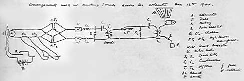
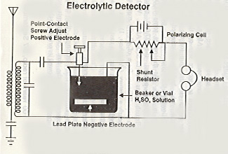
Fessenden was convinced that a successful detector for reception of wireless signals must be constantly receptive, instead of requiring resetting as was the characteristic of the coherer. Although his experiments with wireless receivers began when he was a Professor of Electrical Engineering in the Western University of Pennyslvania, in 1896/97; it was not until 1901/02 that he discovered the electrolytic detector. In 1902 and 1903 he patented the first practical detector [US Patents 706,744 and 727,331] -- which he called a barretter, a name coined from the French word for exchanger. This name implies the exchange of AC for DC, i.e. the device behaved like a rectifier, c.f. [Pickworth, 1994]. In Fig. 5 we sketch one of Fessenden's early radio receivers using this detector; which was the standard of sensitivity for many years until it was replaced by the vacuum tube some ten years later. Fessenden's barretter detector was however useless for reception of unmodulated CW. All that one would hear would be the clicks as the Morse telegraph key was closed and opened. However, very early, some 11 years ahead of its time, Fessenden's fertile mind had already devised a solution. He invented the methodology (and the word) for combining two frequencies to derive their sum and difference frequencies, viz. the heterodyne method of detecting continuous waves (US Pat. No. 706,740 dated 12 August 1902; and Nos. 1,050,441 and 1,050,728 dated 14 January, 1913). But it was not before 1912-1914, when the triode's versatility to be an oscillator, or RF source, was established, that the heterodyne receiver became a practical method for detecting CW. Today, heterodyning is fundamental to the technology of radio communications. Fleming in 1904 invented the valve diode (known as a Fleming valve). The patent which covered its use as a detector of Hertzian waves became the property of the Marconi Company, and eventually, but not until after WWI, Fleming valves were put into operation in Marconi stations. Meanwhile de Forest, who was following the footsteps of Fessenden, experimenting with the electric arc as a CW wireless transmitter for telephony needed a good detector. The electrolytic detector that he had been using was judged by The Courts in 1906 to be an infringement on Fessenden's patent. As a result he had to change all of his stations to use the silicon detector, which had been patented in 1906 by H.H. Dunwoody, an officer in his company. Because of this incident, de Forest resigned from the company in November 1906. De Forest started looking for a better valve detector. He made some Fleming valves, and, in a moment of inspiration, he added a third element, a control element shaped like a grid-iron, called a grid. De Forest patented his audion, the first three-element valve in 1907. Although the audion was more sensitive as a detector than the Fleming valve he was prevented from using it for commercial purposes, by a lawsuit launched by the Marconi Company (claiming infringement in spite of the fact that it was a different valve). De Forest did not understand how the valve operated, and it remained for Langmuir, Armstrong, and van der Pol to discover its full possibilities. The time interval between Fessenden's heterodyne receiver (1902) and Armstrong's "feedback" receiver or regenerative receiver (1913) is the 11 years mentioned above. Armstrong's superheterodyne receiver was not invented until 1918. 4. The First Transatlantic Experiment On 12 December 1901 signals from a high power spark transmitter located at Poldhu were reported to have been received by Marconi and his assistant George Kemp, at a receiving station on Signal Hill, near St. John's, Newfoundland. The signals had traveled a distance of 3500 kilometres. Even at the time of the experiment there were those who said, indeed there are some who still say, that he misled himself and the world into believing that atmospheric noise crackling was in fact the Morse code letter 'S'. A little later, in February 1902, when Marconi returned to England on the SS Philadelphia, using a tuned ship-borne antenna, he received signals using his filings coherer from the same sender up to distances of 1120 km by day and 2500 km by night. Even these distances are rather remarkable considering the receiving apparatus he used. We discuss here in detail that first transatlantic experiment. The Poldhu Station Marconi's ambition at the turn of the century to demonstrate long-distance wireless communication, and develop a profitable long-distance wireless telegraph service, led to his pragmatic proposal in 1900 to send a wireless signal across the Atlantic. He conceived a plan to erect two super-stations, one on each side of the Atlantic, for two-way wireless communications, to bridge the two continents together in direct opposition to the cable company (Anglo-American Telegraph Company). For the eastern terminal, he leased land overlooking Poldhu cove in southwestern Cornwall, England. For the western terminal the sand dunes on the northern end of Cape Cod, MA at South Wellfleet, was chosen. The aerial systems comprised 20 masts, each 61 metres high, arranged in a circle 61 m in diameter. The ring of masts supported a conical aerial system of 400 wires, each insulated at the top and connected at the bottom, thus forming an inverted cone. Vyvyan [1933], the Marconi engineer who worked on the 1901 experiment, when shown the plan, did not think the design sound. Each mast was stayed to the next one, and only to ground in a radial direction, to and away from the centre of the mast system. He was overruled, construction went ahead, and both aerial systems were completed in early 1901. However, before testing could begin catastrophe struck, the Poldhu aerial collapsed in a storm on 17 September, and the South Wellfleet aerial suffered the same fate on 26 November, 1901. At Poldhu Marconi quickly erected two masts and put up an aerial of 54 wires, spaced 1 metre apart, and suspended from a triadic stay stretched between these masts at a height of 45.7 m. The aerial wires were arranged fan shaped, presumably insulated at the top, as was his conical wire aerial, and connected together at the lower end, see Fig. 1. This photograph has been published and republished, and clearly one can see only 12 wires -- but the view generally held is that the aerial system as described above by Vyvyan [1933) is right, that is there were 54 wires, and the photograph has been retouched. The antenna was driven by the curious two stage spark transmitter, previously discussed. There were many problems in getting it to work at the high power levels desired [see Thackeray, 1992]. Our principal concern here is the frequency generated by the Poldhu station. The oscillation frequency is determined by the natural resonant response of the antenna system, which includes the inductance of the secondary of the antenna transformer T2, since in effect the antenna system is a base-loaded monopole (see Fig. 2). The primary of this transformer consisted of 2 7/20 wires in parallel, the secondary consisted of 7 or 9 wires of 7/20 wire in series. Fleming's sketch indicates 9 wires; Entwisle [1922] said there were 7 wires. The inductance values for this transformer have long been debated, since the original transformer is lost, there are no drawings, and reports about them differ [Thackeray, 1992]. G. Garratt made a copy of Ls (the secondary of this transformer) and measured its inductance to be 6 x 10⁻⁶ H [see Ratcliffe 1974]. While the inductance Ls changes the resonant frequency, the exact value does not change the conclusion reached in our study. For Ls equal to 6 x 10⁻⁶ H, we have modelled Marconi's Poldhu antenna, assuming the fan comprised 12 wires. According to the antenna analysis code MININEC, the resonant frequency of the antenna system was 850 kHz. A number of scientists and engineers interested in the actual frequency or frequencies radiated by this first high power transmitter at Poldhu have discussed the possibility that the aerial transformer was overcoupled, resulting in a double-humped frequency/amplitude response. We do know that Fleming tuned the primary oscillatory circuit by varying the discharge capacitor C2 to maximize the aerial current. Since our best estimate for the component values (C2 = 0.037 muF and Lp = 8 x 10⁻⁷ H) would result in a resonant frequency of 925 kHz, it seems logical to conclude that the overall system response would result in a single peak centred on the resonant frequency of the aerial system, viz. about 850 kHz. Historians have also speculated that the transmitter might also have radiated a high-frequency signal as well, since an HF signal would have been more suitable for transatlantic communications (to be discussed), see for example Ratcliffe [1974]. If Marconi had used a thin wire transmitting antenna at Poldhu, this antenna would indeed have radiated efficiently at odd harmonics of the fundamental resonant frequency. But for our model the antenna is inductive for all frequencies greater then the fundamental resonant frequency response of the antenna system. One must conclude therefore that the Poldhu spark-transmitter system radiated efficiently only on the fundamental oscillation frequency of the tuned antenna system -- about 850 kHz. Marconi himself has been evasive concerning the frequency of his Poldhu transmitter. Fleming in a lecture he gave in 1903 said that the wavelength was a 1000 feet or more, say, one-fifth to one-quarter of a mile (820 kHz is the generally quoted frequency). Marconi remained silent on this wavelength, but in 1908 in a lecture to the Royal Institution he quotes the wavelength as 1200 feet, see Bondyopadhyay [1993]. Reception on Signal Hill For his transatlantic experiment, Marconi decided to set up receiving equipment in Newfoundland. In December 1901 he set sail for St. John's, with a small stock of kites and balloons to keep a single wire aloft in stormy weather. A site was chosen on Signal Hill, and apparatus was set up in an abandoned military hospital. A cable was sent to Poldhu, requesting that the Morse letter " S " be transmitted continuously from 3:00 to 7:00 PM local time. On 12th December, 1901, under strong wind conditions, a kite was launched with a 155 m long wire. The wind carried it away. A second kite was launched with a 152.4 m wire attached. The kite bobbed and weaved in the sky, making it difficult for Marconi to adjust his new syntonic receiver which employed the Italian Navy coherer. "Difficult" I will accept, but how he determined the frequency of tuning for his receiver is a mystery to me. Whatever, because of this difficulty, Marconi decided to use his older untuned receiver. History has assumed that he substituted the metal filings coherer previously used with this receiver for the newly acquired Italian Navy coherer, but Marconi never really said he did [see Phillips, 1993]. He referred only to the use of three types of coherers. Despite the crude equipment employed, and in our view the impossibility of hearing the signal, Marconi and his assistant George Kemp convinced themselves that they could hear on occasion the rhythm of three clicks more or less buried in the static, and clicks they would be if heard at all, because of the low spark rate. Marconi wrote in his laboratory notebook: Sigs at 12:30, 1:10 and 2:20 (local time). This notebook is in the Marconi Company archives and is the only proof today that the signal was received. The Enigma Today we know that signals (depending on frequency used) can indeed travel across the Atlantic, and far beyond. But in 1901, anyone who believed that they could, and did, believed so as an act of faith based on the integrity of one man -- Marconi. If 850 kHz was indeed the frequency used, the tests took place at the worst time of day, because the entire path would have been daylight, and the daytime skywave would be heavily attenuated, even though it was a winter day, in sunspot minimum period, and there were no magnetic storms at the time, or for ten days before. The day-time absorption of an ionospherically-reflected signal is a maximum in the LF/MF band. Ratcliffe [1974] has deduced that, from a knowledge only of propagation conditions, reception on Signal Hill is consistent with the observed limiting ranges of reception on the ship only if the untuned landbased receiver was 10-100 times more sensitive than the tuned receiver on the ship. It is therefore difficult to believe that signals could have been heard on Signal Hill, since the receiving equipment after all consisted of a long-wire antenna, coupled to an untuned receiver which had no means of amplification whatsoever, and the type of detector used was less sensitive and its performance unpredictable compared with Fessenden's barretter detector, or the galena crystal detector which evolved a few years later.
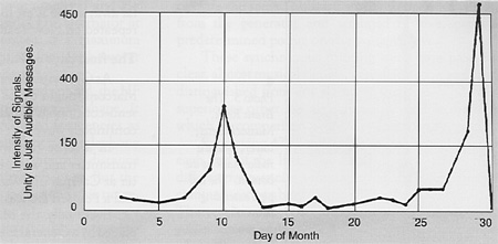
5. The First Radio Propagation Experiments There is no evidence that Marconi made any serious attempt to systematically investigate the charactericistics of the HF, MF and LF portions of the radio frequency spectrum when he began the downward frequency trend, in his struggle to achieve transatlantic wireless communications. He did not do this until 20 years later, in the early 1920's, when attracted to the HF band by amateur radio operators. The radio amateurs had been banished to the then-believed useless frequencies higher than 1500 kHz. The first record showing qualitatively the variation of the intensity of transatlantic messages transmitted between Brant Rock, MA and Machrihanish, Scotland, at night, during the month of January 1906 is reproduced in Fig. 6 [Fessenden, 1908]. Nothing at all was received that month during daytime. It was found (measurements made during 1906) that absorption at a given instant was a function of direction as well as distance, since on a given night the signals received by stations in one direction would be greatly weakened, while there would be less weakening of the signals received by stations lying in another direction; and a few hours or minutes later the reverse would be the case. It was also found that variations of absorption on transatlantic signals appeared to have a quite definite relation with variations of the geomagnetic field, i.e., the greater the absorption the greater the magnetic variation [Fessenden, 1908]. Experiments were made between Brant Rock and the West Indies, a distance of 2735 km, during the spring and summer of 1907. Frequencies in the band 50 kHz to 200 kHz were used. It was found that the absorption at 200 kHz was very much greater than at 80 kHz, and that messages could be successfully received over this path in daytime at the latter frequency. Antenna radiation efficiency was an important factor for frequencies less than 80 kHz. No messages were received in daytime with the higher frequency. The fact that these experiments were made during summer, that the receiving station was in the Tropics (high noise levels), and the fact that the distance, 2735 km was practically the same as between Ireland and Newfoundland was reported by Fessenden [1907]. After publication of the above results, Marconi, in early October, 1907 abandoned his previously used frequencies, and immediately succeeded in operating between Glace Bay and Clifden, a distance of more than 3000 km, the frequency being about 70 kHz. The same messages were received at Brant Rock, MA, a distance of nearly 4825 km. A little later Marconi moved to an even lower frequency, 45 kHz. 6. Verifiable Transatlantic Radio Communications The first East-West transatlantic radio transmission was made during October 1902 from Poldhu, Cornwall to the Italian cruiser Carlos Alberto anchored in the harbour of Sydney, NS with Marconi aboard. The frequency employed was about 272 kHz. This successful transmission was considered an experimental prerequisite to the start-up of the permanent land based wireless Marconi station under construction at Glace Bay, NS. The first West-East transatlantic radio transmission was recorded on 5 December 1902 between Glace Bay and Poldhu. The frequency was about 182 kHz. The first Canada/UK transatlantic radio message (as opposed to hearing the signal) was sent from Glace Bay to Poldhu on 15 December 1902. It was a press message from a London Times correspondent at Glace Bay to his home office. The first USA/UK transatlantic radio message received at Poldhu from the Marconi station at South Wellfleet, MA was from President Roosevelt to King Edward VII, on 18 January, 1903. History has recorded that the above messages were successfully transmitted, but how well these messages were received is a matter of conjecture. In 1902-c.1912, both the Clifden and Glace Bay stations were using "disc discharger" transmitters, and a form of current operated receiver (Marconi's magnetic detector). It is clear that Marconi was still struggling in 1908 to achieve reliable transatlantic radio communications. It is interesting to read a letter written on 19 March, 1909 to Hon. Chauncey M. Depew, US Senate, Washington, DC, signed by five members of The Junior Wireless Club (now The Radio Club of America). The thrust of the letter was to comment on a proposed bill before the Senate, that would in effect restrict the use of the air waves by radio amateurs, because of presumed malicious interference caused by radio amateurs. I quote from a part of that letter, which can be found in the Seventy-Fifth Anniversary Diamond Jubilee Year Book of The Radio Club of America, 1984:
Marconi himself, in his 1909 Nobel Prize address said: "What often happens in pioneer work repeated itself in the case of radiotelegraphy. The anticipated obstacles or difficulties were purely imaginary or else easily surmountable, but in their place unexpected barriers presented themselves, and recent work has been directed to the solutions of problems that were neither expected or anticipated when long distances were first attempted". Certainly after Marconi's first transatlantic radio experiment in 1901, he found that the realization of reliable transatlantic radio communications was more distant (for him) than he realized at the time. The first two-way transatlantic radio telegraphy transmission took place on 10 January 1906, between Fessenden's stations at Brant Rock, MA and Machrihanish Scotland. Repeatedly regular exchange of messages across the Atlantic Ocean took place on most days during winter, spring and into early summer. The frequencies used were in the 80-100 kHz band. The reliability and the quality of signal reception (signal-to-noise ratio) for the Fessenden system must have been very much better than anything Marconi could achieve at this point in time. Fessenden was using his synchronous rotary-spark transmitters at both ends, and tuned receivers with his barretter detector. The signals were superior to other signals used at the time, which by comparison were rough and ragged. His antenna system was an umbrella top-loaded radiator 128 metres high. The Marconi antennas were multi-wire conical structures, or wire antennas with extensive top loading, 61 metres high. Since the radiation efficiency of electrically short antennas varies (approximately) as the height of the antenna red, Fessenden's antenna systems were probably four times more efficient than Marconi's. Radio telephony At the turn of the century Fessenden was using a spark transmitter, employing a Wehnelt interrupter operating a Ruhmkorff induction coil. In 1899 he noted, when the key was held down for a long dash, that the peculiar wailing sound of the Wehnelt interrupter could be clearly heard in the receiving telephone. He must have had a detector of some sort that was working for him, even at this early stage in the development of wireless. This suggested to him that by using a spark rate well above voice band (10,000 sparks/sec), wireless telephony could be achieved; and this he did transmitting speech over a distance of 1.5 km on 23 December 1900, between 15 metre masts on Cob Island, MD [Belrose, 1994a; 1994b]. In autumn of 1906 Fessenden had his HF alternator working adequately on frequencies up to about 100 kHz. About midnight in November, 1906 Mr. Stein at Fessenden's Brant Rock station was telling the operator at a nearby test station at Plymouth, MA how to run the HF alternator. It was usual for these two operators to use speech over this short distance. However his voice was heard by Mr. Armor at Machrihanish, Scotland with such clarity that there was no doubt about the speaker, and the station log books confirmed the report. Fessenden's equipment was working exceptionally well in the early hours of that morning, and (remarkable for that time) the echo of the telegraphy signals from the Scotland station could clearly be heard one fifth of a second later, having travelled the long way around the earth. The Machrihanish tower crashed to the ground on 5 December, 1906 during a severe winter storm. The station was never rebuilt, and so Fessendeil's transatlantic experiments came to an abrupt end. Fessenden's greatest success took place on Christmas Eve 1906, when he and his colleagues presented the world's first wireless broadcast. The transmission included a speech by Fessenden and selected music for Christmas. Fessenden played Handel's Largo on the violin. That first broadcast, from his transmitter at Brant Rock, MA was heard by radio operators on board US Navy and United Fruit Company ships equipped with Fessenden's wireless receivers at various distances over the South and North Atlantic, and in the West Indies. The wireless broadcast was repeated on New Year's Eve. The transmitter was an HF alternator, in which one terminal was connected to ground, the other terminal to the tuned antenna, and a carbon microphone was inserted in the antenna lead. Recall that Fleming, in the first edition of his book on Electromagnetic Waves published in 1906, stated that an abrupt impulse was a necessary condition for wireless transmission, and that high frequency currents, even of sufficient frequency could not produce radiation. The highest frequency of HF alternators prior to the summer of 1906 was about 10 kHz. This belief, and an earlier belief that the terminals of an antenna had to be bridged by a spark, show how wrong some of the early "experts" were. Continuing in the same vein, Fessenden in his 1908 paper restated his long held view: "The coherer is well adapted for working with damped waves, but the coherer-damped wave method can never be developed into a practical telegraph system. It is a question whether the invention of the coherer has not been on the whole a misfortune as tending to lead development of the art astray into impracticable and futile lines, and thereby retarding the development of a really practical system". 7. Concluding Remarks There are those that say that Marconi's greatest triumph (the mother of all experiments) was when he succeeded in 1901 in passing signals across the Atlantic. There are those that say that he misled himself and the world into believing that atmospheric noise crackling was in fact the Morse code letter 'S'. Whether Marconi heard the three faint dots or not is really unimportant. His claim "sparked" a controversy among contemporary scientists and engineers about the experiment that continues today. Certainly engineers and scientists of the present day are unanimous in admiring the bold and imaginative way in which Marconi attempted to take one spectacular step forward, to extend the range of wireless communications from one or two hundred kilometres to the 3500 kilometre distance across the Atlantic ocean. The world has acclaimed Marconi as the "father of wireless", although some say that Alexander Popov and Oliver Lodge were first in the field. History has accredited Marconi with the invention of an early form of radio telegraphy. Fessenden's continuous waves, a new type of detector, and, his invention of the method as well as the coining of the word heterodyne, did not by any means constitute a satisfactory wireless telegraphy or wireless telephony system, judged by today's standards. They were, however, the first real departure from Marconi's damped-wave-coherer system for telegraphy which other experimenters were merely imitating or modifying. They were the first pioneering steps toward radio communications and radio broadcasting. Today, heterodyning is fundamental to the technology of radio communications. Some historians consider that Fessenden's heterodyne principle is his greatest contribution to radio science. Edwin Howard Armstrong's super-heterodyne receiver is based on the heterodyne principle. Except for method improvement Armstrong's superheterodyne receiver remains the standard radio receiving method today. Fessenden, a genius, and a mathematician was the inventor of radio as we know it today. References Alexanderson, E.F.W. [1919], "Transatlantic Radio Communication", Trans. AIEE, pp. 1077-1093. Austin, B.A. [1994], "Oliver Lodge - The Forgotton Man of Radio?", The Radioscientist & Bulletin, Vol. 5, No. 4. pp. 12-16, URSI, Gent, Belgium. Belrose, J.S. [1994], "Fessenden and the Early History of Radio Science', Radioscientist & Bulletin, Vol. 5, No. 3, URSI, Gent, Belgium, pp. 94-110. Belrose, J.S. [1994], "Sounds of a Spark Transmitter", multimedia article published on URSI Radioscientist On-Line on the World Wide Web. Address is: http://newton.otago.ac.nz.:808/trol/Rolhome.htmi Bondyopadhyay, P.B. [1993], "Investigations on the Correct Wavelength of Transmission of Marconi's December 1901 Transatlantic Wireless Signal", IEEE Antennas and Propagation Society, International Symposium Digest, Vol. 1, pp. 72 -75. Entwisle [1922], "Year Book of Wireless Telegraphy", Wireless Press. Fessenden, R.A. [19071, The Electrician (London), July 26. Fessenden, R.A. [1908], "Wireless Telephony", A paper presented at the 25th annual convention of the American Institute of Electrical Engineers, Atlantic City, NJ, June 20, 1908. Phillips, V.J. [1993], "The 'Italian Navy Coherer' affair turn-of-the-century scandal", IEE Proceedings A, Vol. 140, pp. 175-185. Pickworth, G. [1994], "Detection before the diode", Electronics World + Wireless World, December 1994, pp. 1003-1006; and January 1995, pp. 28-30. Ratcliffe, J.A. [1974], "Scientists' reactions to Marconi's transatlantic radio experiment', Proc. IEE, 121, pp. 1033-1038. Thackeray, D. [1992], "The First High-Power Transmitter at Poldhu', The AWA Review, Vol. 7, pp 29-45. Vyvyan, R.N. [1933], "Marconi and his Wireless", EP Publishing, 1974. First published as "Wireless over 30 Years", by Routledge and Keegan. References Not Cited "Guglielmo Marconi", compiled by Pam Reynolds published by the Marconi Company, Chelmsford, 1984. "Marconi Towers - Proposals for the Preservation and Development of the Marconi Historic Site" A Study for Marconi Museums Association, PO Box 156, Marion Bridge, NS. "Register of the George H. Clark Radioana Collection c. 1880-1950", by Robert S. Harding, Archives Center, National Museum of American History, Washington, DC, 1990. Reprinted courtesy of John S. Belrose, Communications Research Centre Canada |
|
All the concepts, methods, designs and devices presented on this
web site
|

|
All rights reserved. Copyright © 1985- Francesco Errante |